-
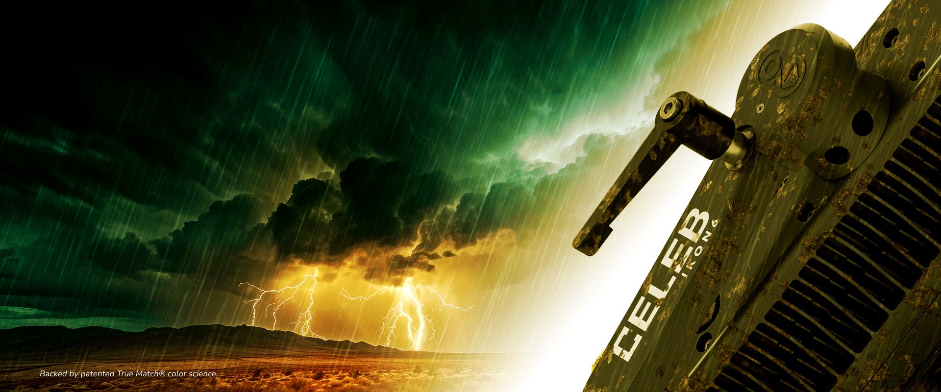

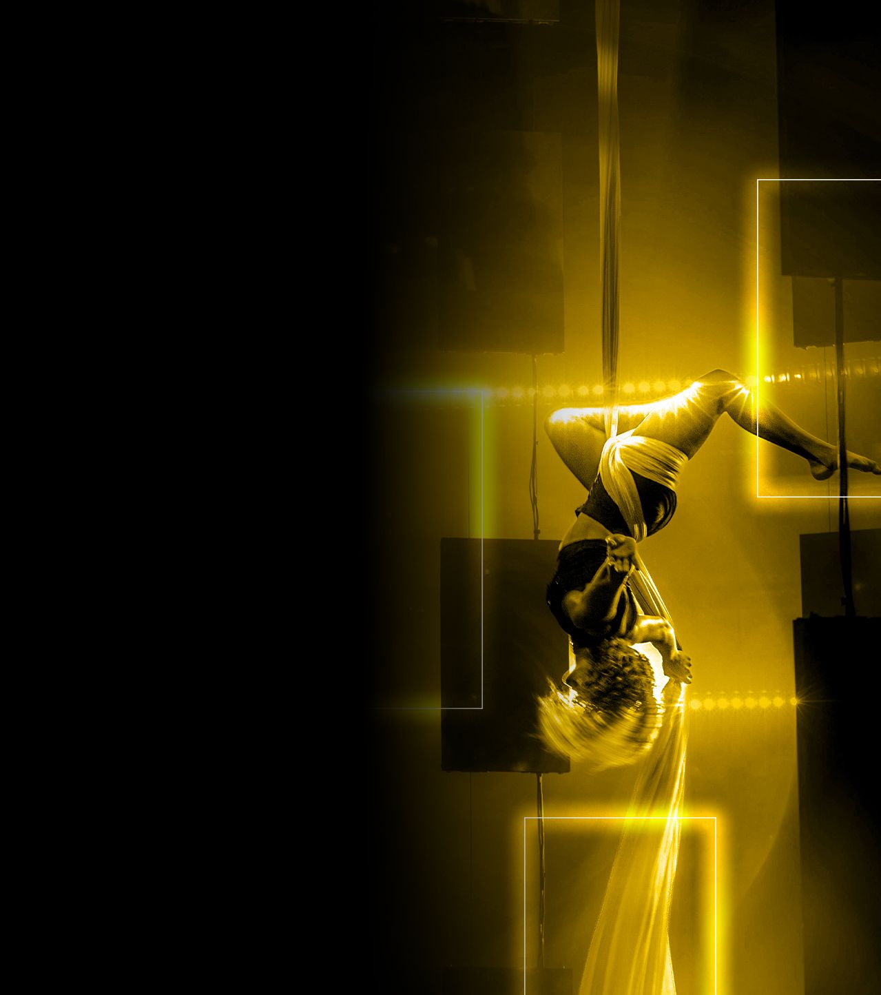
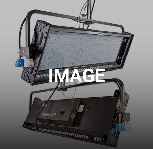
Who is the real star?
Whatever the future or the elements bring.
COMING SOON!
-


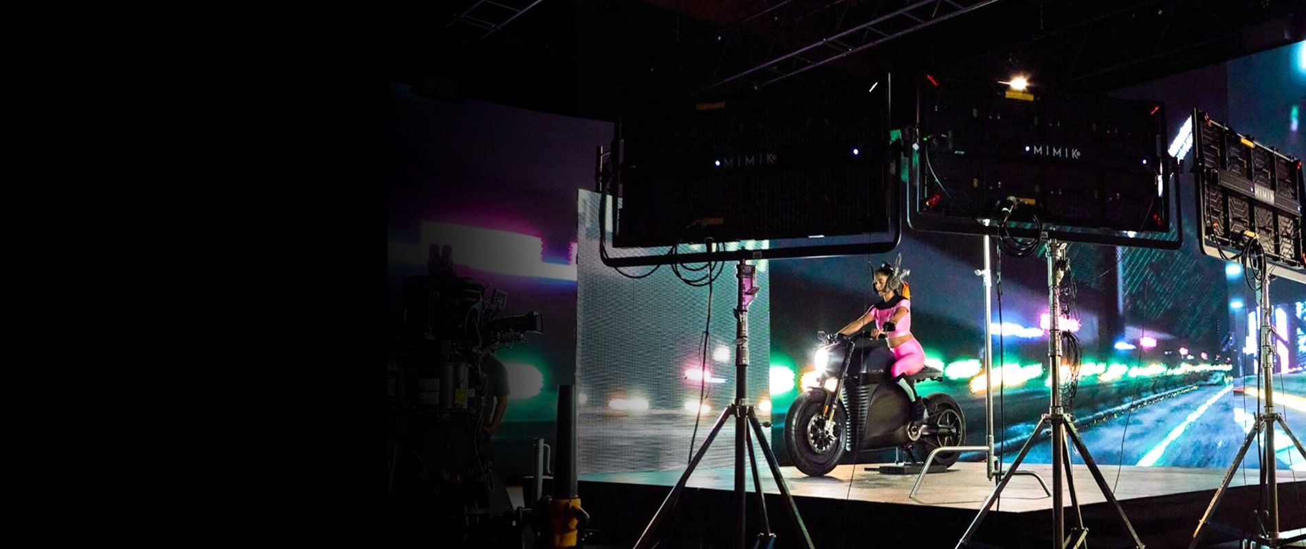
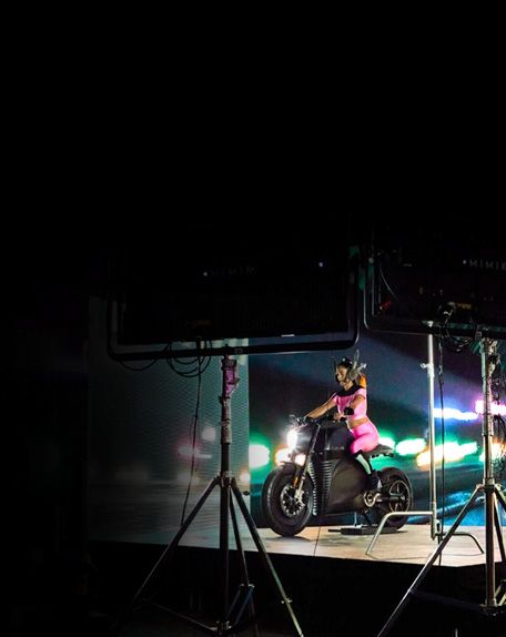
REACH ACROSS WORLDS
See the Physical and Digital converge at NAB.
APRIL 14–17, 2024, BOOTH C6430Las Vegas Convention Center VIP CODE: NS9638
-
-
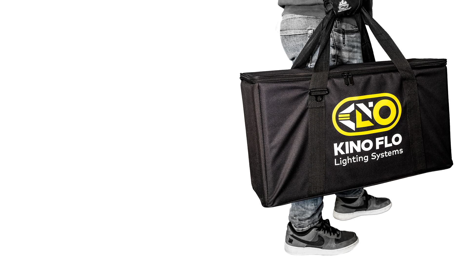
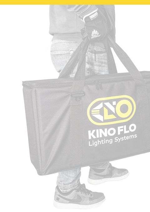
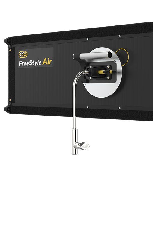
Spring is here.
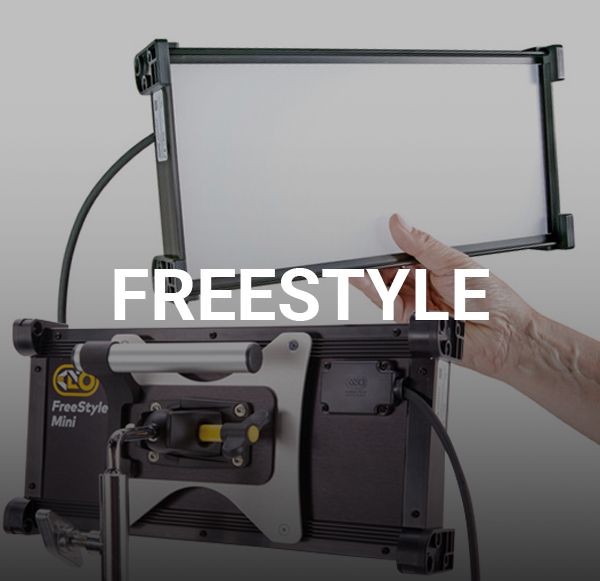
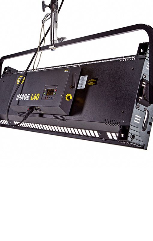
The season for new mobility!Bring in your fluorescent gear.
Walk out with FreeStyle Air. -
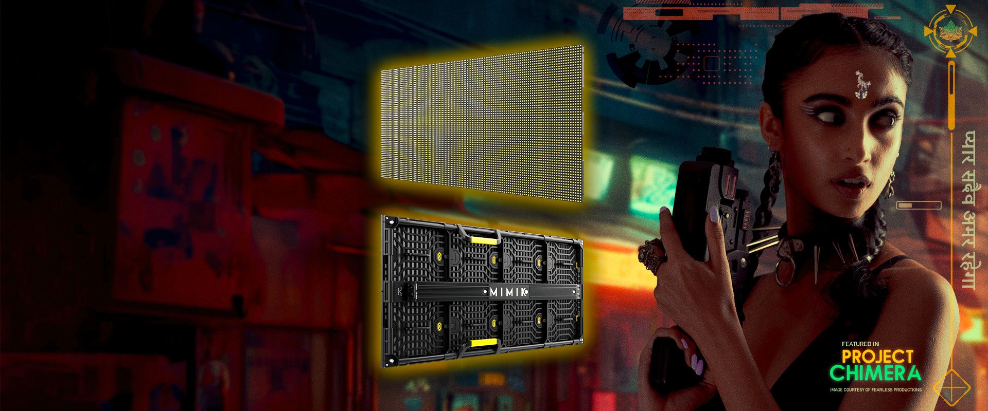
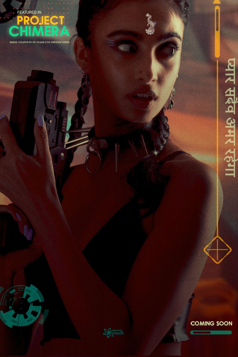
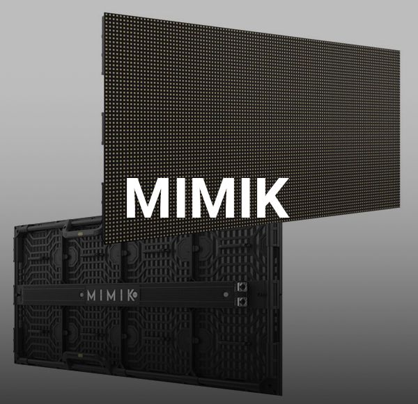
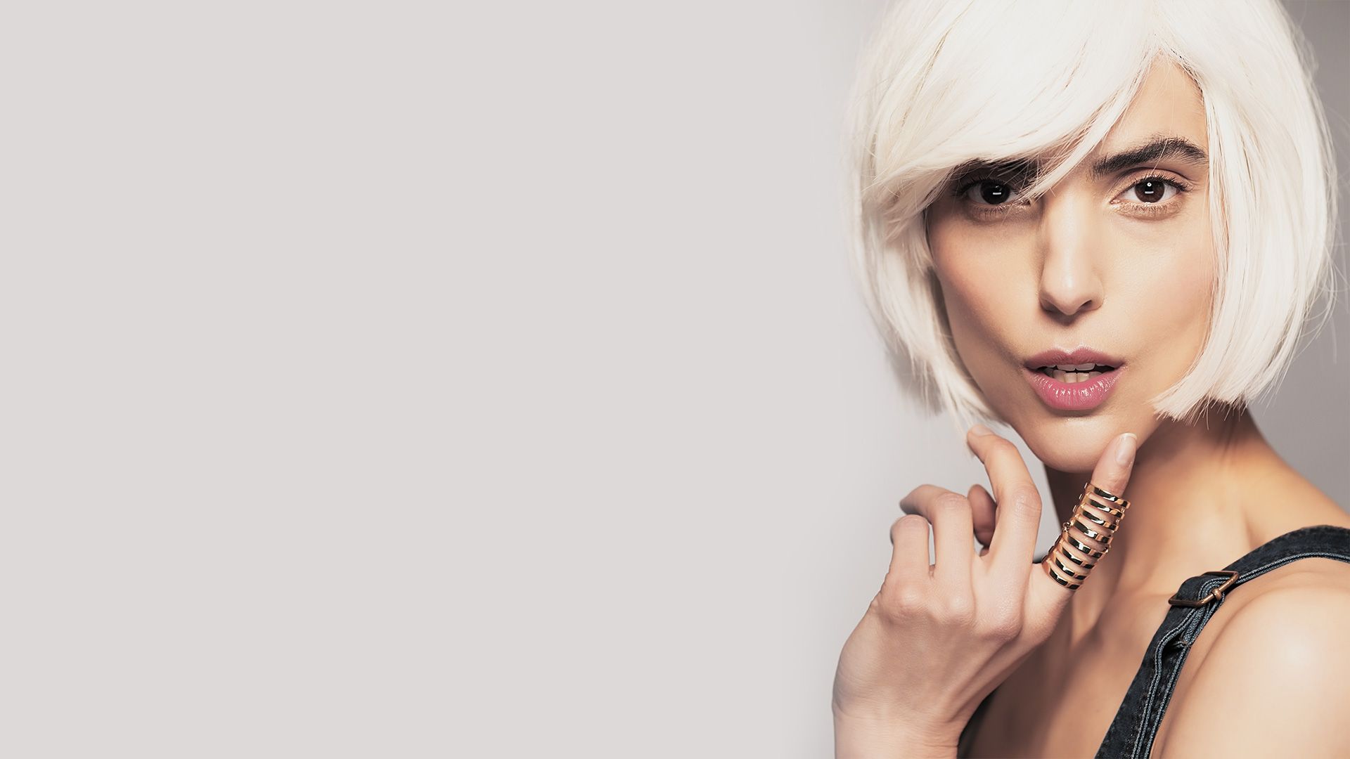
Full-spectrum image based lighting to achieve utmost realism.
-
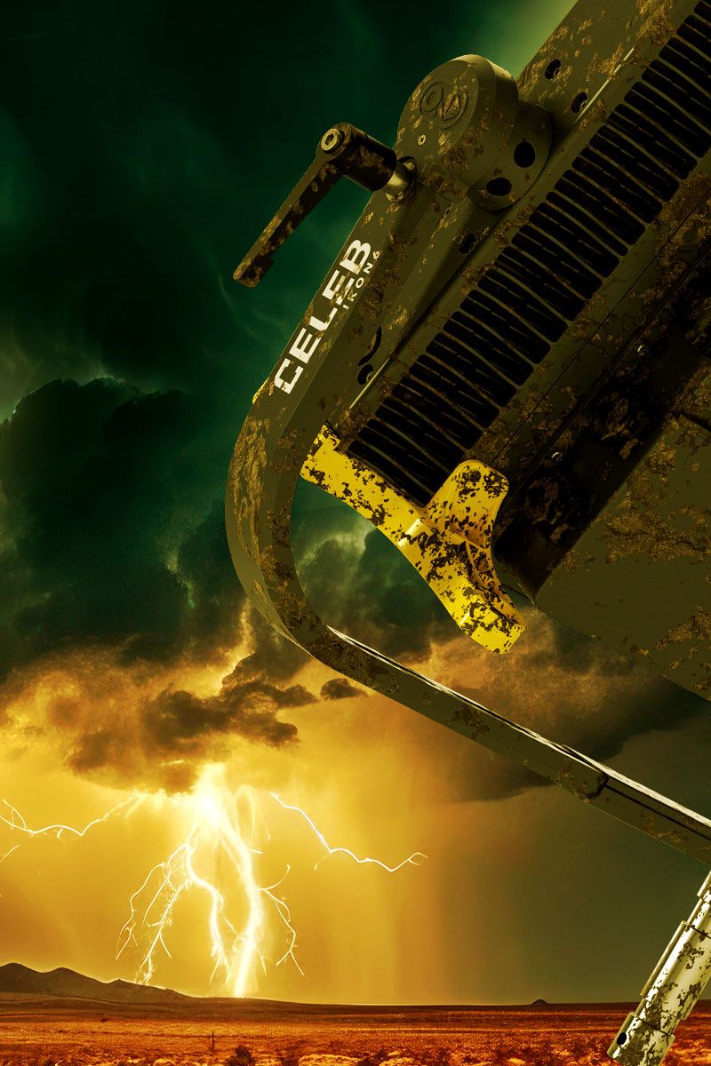
Who is the real star?
Whatever the future or the elements bring.
COMING SOON!
-
REACH ACROSS WORLDS
See the Physical and Digital converge at NAB.
APRIL 14–17, 2024, BOOTH C6430Las Vegas Convention Center VIP CODE: NS9638
-
-
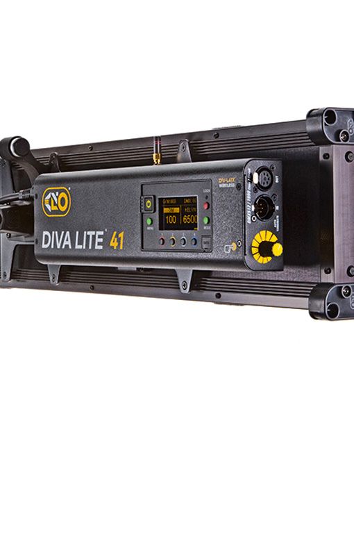
Spring is here.
The season for new mobility!Bring in your fluorescent gear. Walk out with FreeStyle Air.
-
Full-spectrum image based lighting to achieve utmost realism.
-
True Match® firmware is now available for Kino Flo LED lighting. This free firmware update includes camera LUTs that optimize the LED output to the color science of some of the most popular digital cinema cameras.
HOUSE OF BRANDS